I have an inspection scope camera that I’m attempting to repair. It’s one with a camera on the end of a flexible rod to see into tight spaces. The pins that lead to the camera came out of the connector. I tried looking for teardowns or even replacement parts, but found nothing.
Two pins are still inserted, but I’m not confident they are in the right places. I want to get it working without the risk of frying everything. I’ve done my best to find where each pin goes, but there’s not enough info for me figure it out on my own. The camera rod also includes an LED for light.
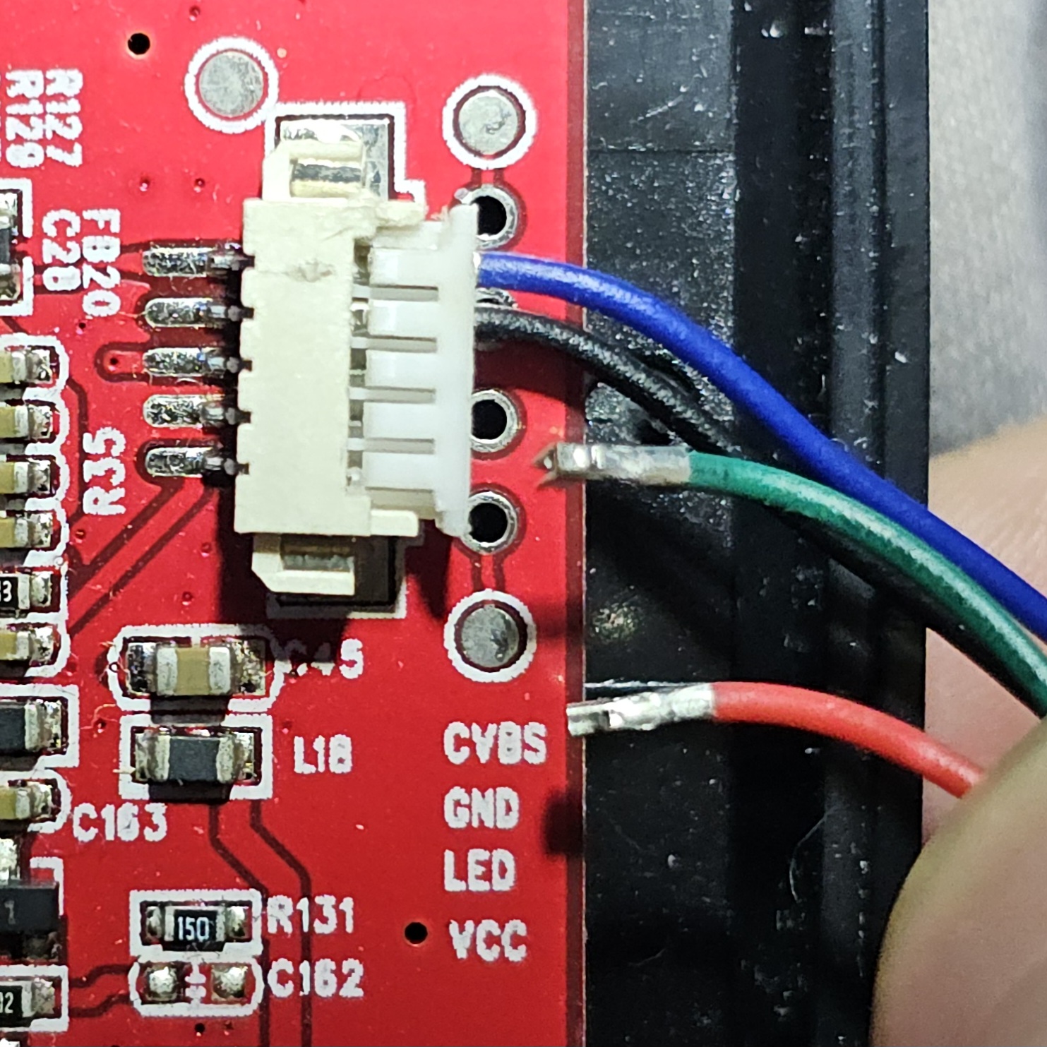
Here’s a photo of the connector as it is:
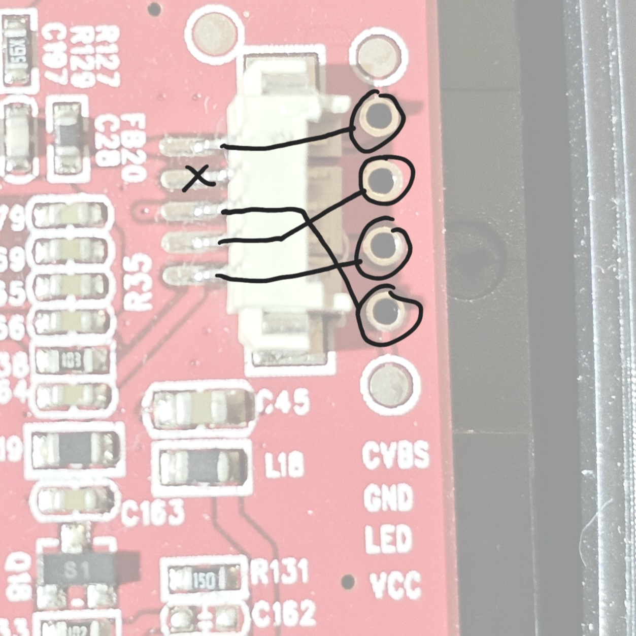
And here is the socket with it’s pins labeled (the labels correspond to the testing pads and not to the socket pins):
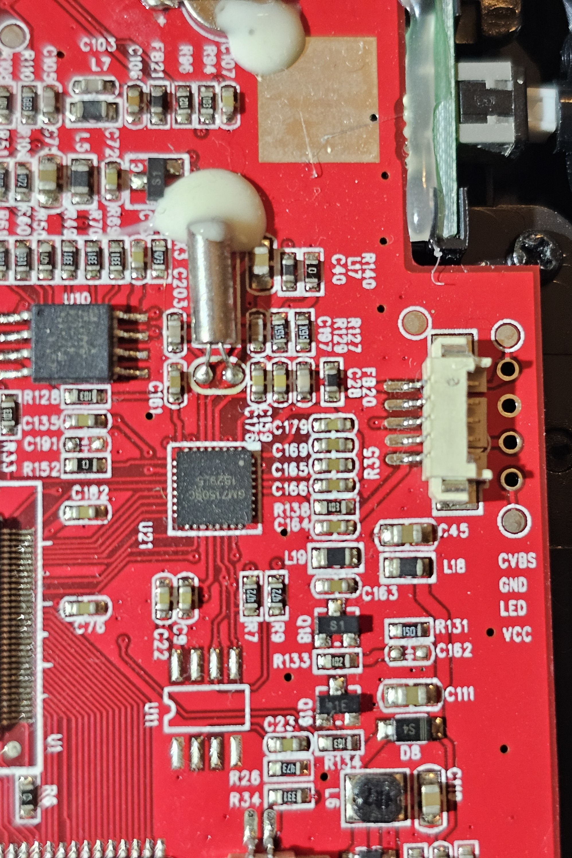
Here’s a zoomed out pic if it’s of any use:
I have a multimeter, so I can do any testing you can suggest. Unfortunately, I was not able to disassemble the camera to trace any wires.
Its a JST type connector I think. I bet if you check digikey (or whatever supplier you use), you’ll be able to find kits for replacing the connector and its pins. Looks like the silkscreen labels on the right edge of the board below the connector show the pinout order.
Edit: on second thought, that labeled pinout may only be for the through-hole solder points. Safest bet would be to just identity the wires and solder them accordingly, rather than mess with the connector.
EDIT: also before starting any of this, unplug the camera and check voltage between GND and VCC on a powered up board. Check if the voltage seems at all plausible to power up the camera. Usually it will be 3.3V or 5V. Does the board by itself show any signs of life when powered on?
The connector type is probably JST PH 2, but to confirm that you’d have to provide it’s dimensions. If the pins are falling out on their own, it would be wise to replace the plug. Terminals look fine.
If you can’t disassemble the camera, then well… You might have to take a risk.
Usually, but not necessarily, black wire is GND, red VCC. Assuming they are, you can plug those two wires alone and attempt to power the device on.
Next you can switch your multimeter to DC voltage measuring, apply black probe to GND and try applying red probe to green and blue wire terminals. On LED wire there should be no voltage present (close to 0V), and on video signal wire you should be seeing some weird low voltage, possibly changing depending what the camera is looking at.
This is of course all under the assumption that power wires were guessed correctly. If not, it may release it’s magic smoke.
I have the pin order now!

I (very carefully) tested the pins for a brief moment to verify it all was working.
First I verified the voltage of vcc as 3.5v. Red to that and black to ground worked with no problems.
I figured the blue was probably in it’s correct place so I tried it and got video.
Quick test with green have me LED power.
The male part of the plug is borked, so I’ll just solder the wires on. Might even fashion up my own plug if I’m feeling fancy. I’m sure I got some spare connectors lying around somewhere.
Glad you’ve figured that out!
The second connector pin from the bottom is connected to what’s almost certainly a ground pour, and this is in line with the through hole labels together with your diagram. This is your black wire.
I would bet money on the rest of the labels (and your diagram) being correct too, so red wire goes to middle connector pin.
If you’re fairly certain that blue is in its correct location then we’re done: green goes to bottom pin. If you are not, we can take a closer look.
From the top down, that would be
Blue X Red Black GreenYour order is correct!
With the help of the other comment suggesting to measure the voltage of VCC, I was able to verify all the pins were working.
Good job
It looks as though this is a 5 pin connector, and you are saying that the second pin from the top is not connected but the black wire looks like it’s in that spot. Black is often used for ground, is it possible that the second pin connects to ground instead of one of the through holes? It also looks like there are labels right below the holes that tell you what they are for. If I had to guess, black is ground and red is VCC. The other two are a bit of a mystery, but if you know that the blue wire goes up top then the green is probably the LED. This is all a guess, I don’t actually know. So from the top it might be blue, black, green and then red. You could theoretically just clip the crimps off the wires and solder them in, it’s the quickest and cheapest way. The more correctly way to fix it would be to identify the connector, and buy a crimping kit for that style connector. Common brands are Molex, Amphenol, and JST. It’s probably a JST or a knock off, but they make a boatload of different products. Are there any numbers on either the socket or plug?